Essay
In the cross-coupled oscillator circuit shown in Fig. 15.1.1, represents the loss of each inductor. Each transistor is operating at a transconductance and has an output resistance . Find the oscillation frequency and explain why the circuit oscillates at this frequency. Also, derive an expression for the minimum value of needed to obtain sustained oscillations.
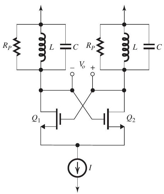
Figure 15.1.1
Correct Answer:
Verified
Figure 15.1.2
Figure 15.1.2 shows the...
View Answer
Unlock this answer now
Get Access to more Verified Answers free of charge
Related Questions