In the circuit of Fig. 11.7.1 (refer to Figure below), assume that coupling capacitors and are very large and thus act as perfect short circuits at
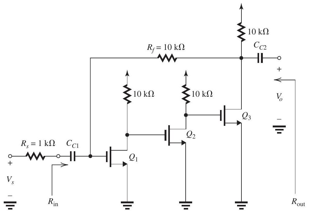
Figure 11.7.1
the frequencies of interest. Transistors , and are identical and are operating at identical dc bias conditions so that each has and .
(a) Replacing the signal source and with its Norton's equivalent circuit, show that this feedback amplifier utilizes the shunt-shunt feedback topology.
(b) Give the circuit and determine the value of .
(c) Give the ideal value of the closed-loop gain and hence of the voltage gain .
(d) Provide the circuit and determine the values of , and .
(e) Find the values of , and .
(f) Find the actual value of voltage gain realized and compare to the approximate value found in (c).
(g) Find the value of ,
(h) Find the value of .
(i) If is , find the magnitudes of the signals at the gates of , and and at the output (i.e., ).
Correct Answer:
Verified
Q1: An amplifier with an open-loop gain
Q2: Q3: Q4: Q5: The feedback voltage amplifier in Fig. Q6: Figure 11.6.1 (refer to Figure below) Q8: Q9: Unlock this Answer For Free Now! View this answer and more for free by performing one of the following actions Scan the QR code to install the App and get 2 free unlocks Unlock quizzes for free by uploading documents![]()
![]()
![]()
![]()
![]()