The Feedback Voltage Amplifier in Fig R1 And R2 the Following Component Values Are Given
Question 5
Question 5
Essay
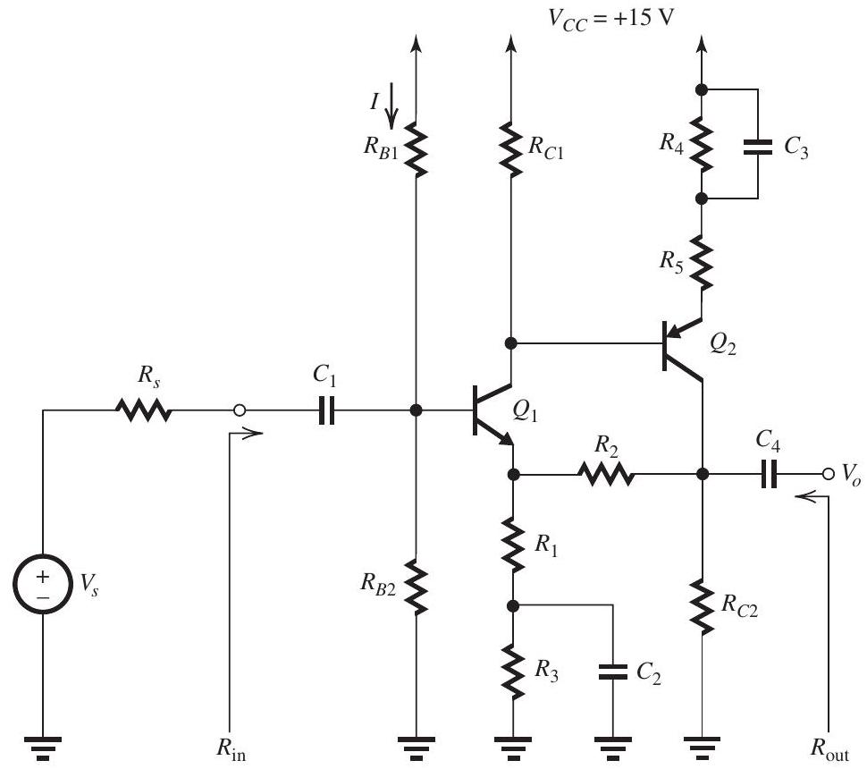
The feedback voltage amplifier in Fig. 11.5.1 Figure 11.5.1 utilizes the series-shunt feedback topology with the feedback network composed of R1 and R2 . The following component values are given: RS=5kΩ,R1=1kΩ,R2=11kΩ , and R5=300Ω . The BJTs have β=100 , ∣VBE∣=0.7V , and ro=∞ . The capacitors C1,C2 , C3 , and C4 are very large. (a) Find values for RB1,RB2,R3,RC1,R4 , and RC2 so as to establish the following de conditions: VB1=+4V,VC1=+6V,VC2=+4V,IE1=IE2=1mA , and I=0.1mA . Hint: Do as many of your calculations as possible on Fig. 11.5.1 on the exam paper. (b) Supply the A circuit and find the values of A , Ri , and RO . (c) Supply the β circuit and find the value of β . (d) Find the closed-loop gain Af≡Vo/Vs , the input resistance Rin , and the output resistance Rout.
Correct Answer:
Verified
Refer to Figure 11.5.1 below and Figure ...
View Answer
Unlock this answer now Get Access to more Verified Answers free of charge