Multiple Choice
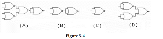
-Which circuit in Figure 5- 4 represents the NOR implementation of an OR gate?
A) Figure (A)
B) Figure (B)
C) Figure (C)
D) Figure (D)
Correct Answer:
Verified
Related Questions
Q23: Which circuit is the logical equivalent of
Q24: When the inverted output of one gate
Q25: Why are multiple NAND gates often used
Q26: Which of the figures is the correct
Q27: The relationship between a NOR gate and
Unlock this Answer For Free Now!
View this answer and more for free by performing one of the following actions

Scan the QR code to install the App and get 2 free unlocks

Unlock quizzes for free by uploading documents