For the circuit shown in the figure, R1 = 50 ?, R2 = 20 ?, R3 = 35 ?, R4 = 10 ?, R5 = 68 ?, I1 = 0.111 A, I2 = 0.142 A, and the batteries are ideal.
(a)Determine V1 and V2.
(b)What is the potential difference across R4? 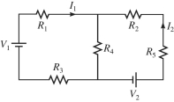
Correct Answer:
Verified
View Answer
Unlock this answer now
Get Access to more Verified Answers free of charge
Q105: Determine the current in the 8.0-Ω resistor
Q106: Four resistors are connected across an ideal
Q107: For the circuit shown in the
Q108: For the circuit shown in the figure,
Q109: Determine the current in the 7.0-Ω resistor
Q111: In the circuit shown in the figure,
Q112: For the circuit shown in the figure,
Q113: Three resistors with resistances of 2.0 Ω,
Q114: Four resistors are connected across an ideal
Q115: In the circuit shown in the figure,
Unlock this Answer For Free Now!
View this answer and more for free by performing one of the following actions

Scan the QR code to install the App and get 2 free unlocks

Unlock quizzes for free by uploading documents