For the circuit shown in the figure, the ideal battery has an emf ? = 80 V. The four resistors have resistances of and Calculate the rate at which heat is being generated in the resistor R4. 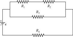
Correct Answer:
Verified
Q102: Three resistors with resistances of 2.0 Ω,
Q103: For the circuit shown in the figure,
Q104: In the circuit shown in the figure,
Q105: Determine the current in the 8.0-Ω resistor
Q106: Four resistors are connected across an ideal
Q108: For the circuit shown in the figure,
Q109: Determine the current in the 7.0-Ω resistor
Q110: For the circuit shown in the figure,
Q111: In the circuit shown in the figure,
Q112: For the circuit shown in the figure,
Unlock this Answer For Free Now!
View this answer and more for free by performing one of the following actions

Scan the QR code to install the App and get 2 free unlocks

Unlock quizzes for free by uploading documents