For the circuit shown in the figure, R1 = 50 Ω, R2 = 20 Ω, R3 = 35 Ω, R4 = 10 Ω, R5 = 68 Ω, I1 = 0.111 A, I2 = 0.142 A, and the batteries are ideal.
(a) Determine V1 and V2.
(b) What is the potential difference across R4? 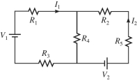
Correct Answer:
Verified
View Answer
Unlock this answer now
Get Access to more Verified Answers free of charge
Q132: In the circuit shown in the figure,
Q133: Determine the current in the 12-Ω resistor
Q134: For the circuit shown in the figure,
Q135: A multiloop circuit is shown in the
Q136: Determine the current in the 18-Ω resistor
Q138: Determine the current in the 7.0-Ω resistor
Q139: A multiloop circuit is shown in the
Q140: For the circuit shown in the figure,
Q142: In the circuit shown in the figure,
Q203: A 2.0-μF capacitor that is initially uncharged
Unlock this Answer For Free Now!
View this answer and more for free by performing one of the following actions

Scan the QR code to install the App and get 2 free unlocks

Unlock quizzes for free by uploading documents