For the circuit shown in the figure, R1 = 18 Ω, R2 = 44 Ω, R3 = 33 Ω, R4 = 14 Ω, R5 = 12 Ω, V1 = 18 V, V2 = 12 V, and the batteries are ideal. Determine I1 and I2. 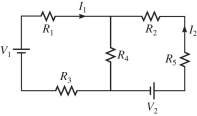
Correct Answer:
Verified
View Answer
Unlock this answer now
Get Access to more Verified Answers free of charge
Q123: For the circuit shown in the figure,
Q124: An ideal 10.0-V dc is connected
Q125: In the circuit shown in the figure,
Q126: In the circuit shown in the figure,
Q127: Determine the current in the 8.0-Ω resistor
Q129: A multiloop circuit is shown in the
Q130: For the circuit shown in the figure,
Q131: Determine the current in the 4.0-Ω resistor
Q132: In the circuit shown in the figure,
Q133: Determine the current in the 12-Ω resistor
Unlock this Answer For Free Now!
View this answer and more for free by performing one of the following actions

Scan the QR code to install the App and get 2 free unlocks

Unlock quizzes for free by uploading documents