The network shown is assembled with uncharged capacitors X , Y, and Z, with CX = 4.0 μF, CY = 6.0 μF, and CZ = 5.0 μF. The switches S1 and S2 are initially open, and a potential difference Vab = 120 V is applied between points a and b. After the network is assembled, switch S1 is then closed, but switch S2 is kept open. What is the final potential difference across capacitor X? 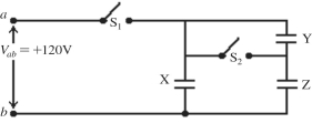
A) 120 V
B) 82 V
C) 75 V
D) 67 V
E) 60 V
Correct Answer:
Verified
Q66: What resistance must be connected in parallel
Q68: Three 2.0-Ω resistors are connected to form
Q69: The capacitive network shown in the figure
Q70: The network shown is assembled with
Q72: A 9.00-µF and a 12.0-µF capacitor are
Q73: Five 2.0-Ω resistors are connected as shown
Q74: Two resistors in series are equivalent to
Q75: The resistors in the circuit shown
Q76: What different resistances can be obtained by
Q149: A 2.0-Ω resistor is in series with
Unlock this Answer For Free Now!
View this answer and more for free by performing one of the following actions

Scan the QR code to install the App and get 2 free unlocks

Unlock quizzes for free by uploading documents