In the circuit shown in Figure 7-29 (a) ,the base voltage can be calculated by 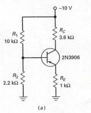
A) using the voltage divider rule using R1 and R2 and the supply voltage.
B) using the voltage divider rule using RC and RE and the supply voltage.
C) multiplying collector current by the collector resistor.
D) multiplying emitter current by the emitter resistor.
Correct Answer:
Verified
Q40: Collector-feedback bias is more effective than emitter-feedback
Q41: The voltage measured across the base-emitter junction
Q42: In order to determine the emitter current
Q43: The schematic diagram of a pnp transistor
Q44: In Figure 7-21,what effect do the capacitors
Q45: In order to calculate the base voltage
Q46: With ambiguous troubles,the troubleshooter very often must
A)
Q47: What should a troubleshooter do if the
Q48: Once the base voltage has been calculated
Q50: Whenever you have a circuit with npn
Unlock this Answer For Free Now!
View this answer and more for free by performing one of the following actions

Scan the QR code to install the App and get 2 free unlocks

Unlock quizzes for free by uploading documents