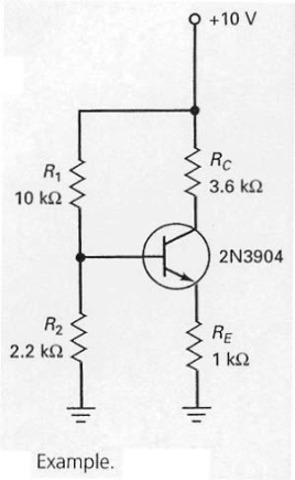
In the circuit shown in Figure 7-12,the first step in finding the emitter current is to determine the voltage across R2.
Correct Answer:
Verified
Q7: Emitter-feedback bias is also called self-bias.
Q8: Emitter-feedback and collector-feedback are typically not adequate
Q9: The emitter-base junction voltage of the silicon
Q10: In the circuit shown in Figure 7-26,if
Q11: In the circuit shown in Figure 7-26,if
Q13: Voltage-divider bias is really emitter bias in
Q14: Collector-feedback bias is also called
A) self-bias.
B) collector
Q15: A well-designed voltage-divider bias circuit is one
Q16: Since voltage-divider bias is derived from emitter
Q17: Some electronic equipment has a power supply
Unlock this Answer For Free Now!
View this answer and more for free by performing one of the following actions

Scan the QR code to install the App and get 2 free unlocks

Unlock quizzes for free by uploading documents