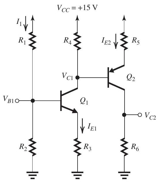
Solved

Figure 651
Design the Circuit in Fig I1=I_{1}= 0.1 mA,VB1=+4 V,IE1=1 mA,VC1=+6 V0.1 \mathrm{~mA}, V_{B 1}=+4 \mathrm{~V}, I_{E 1}=1 \mathrm{~mA}, V_{C 1}=+6 \mathrm{~V}

Question 5

Essay

     Figure 6.5.1 Design the circuit in Fig. 6.5.1 to obtain  I_{1}=   0.1 \mathrm{~mA}, V_{B 1}=+4 \mathrm{~V}, I_{E 1}=1 \mathrm{~mA}, V_{C 1}=+6 \mathrm{~V} ,  I_{E 2}=2 \mathrm{~mA} , and  V_{C 2}=+4 \mathrm{~V} . Let  \beta_{1}=\beta_{2}=100  and  \left|V_{B E}\right|=0.7 \mathrm{~V} . Specify the required values of all resistors.

Figure 6.5.1
Design the circuit in Fig. 6.5.1 to obtain I1=I_{1}= 0.1 mA,VB1=+4 V,IE1=1 mA,VC1=+6 V0.1 \mathrm{~mA}, V_{B 1}=+4 \mathrm{~V}, I_{E 1}=1 \mathrm{~mA}, V_{C 1}=+6 \mathrm{~V} , IE2=2 mAI_{E 2}=2 \mathrm{~mA} , and VC2=+4 VV_{C 2}=+4 \mathrm{~V} . Let β1=β2=100\beta_{1}=\beta_{2}=100 and VBE=0.7 V\left|V_{B E}\right|=0.7 \mathrm{~V} . Specify the required values of all resistors.

Correct Answer:

verifed

Verified

blured image

Figure 6.5.2
Figure 6.5.2 shows the c...

View Answer

Unlock this answer now
Get Access to more Verified Answers free of charge

Related Questions

Unlock this Answer For Free Now!

View this answer and more for free by performing one of the following actions

qr-code

Scan the QR code to install the App and get 2 free unlocks

upload documents

Unlock quizzes for free by uploading documents