The diagram shown is that of a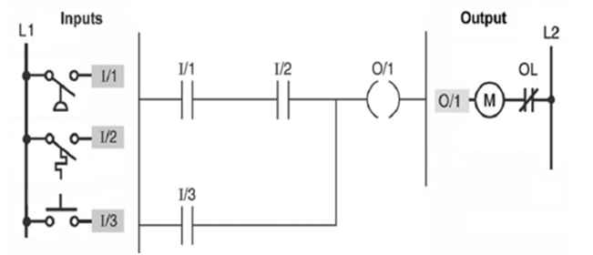
A) relay schematic.
B) ladder logic program.
C) input module wiring diagram.
D) output module wiring diagram.
Correct Answer:
Verified
Q18: The programming device
A)is used to enter the
Q19: Basically, the function of a PLC is
Q20: The scan time is the time required
A)to
Q21: PLCs have sporadic reliability.
Q22: The diagram shown is that of a
Q23: Which module of the PLC connects directly
Q24: Most PLCs can now be programmed using
Q26: The PLC power supply module normaly is
Q27: PLC software that runs on a personal
Q28: In order to energize the starter coil
Unlock this Answer For Free Now!
View this answer and more for free by performing one of the following actions

Scan the QR code to install the App and get 2 free unlocks

Unlock quizzes for free by uploading documents