 Figure 4
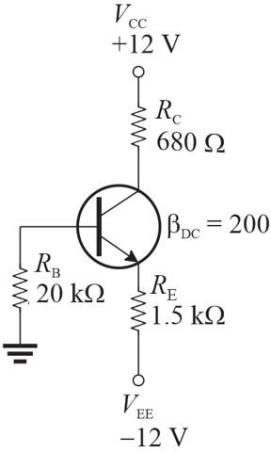
-Refer to Figure 4. If you wanted to develop the equation for IE,
A) assume VCE = VRC; apply Ohm's law to find IC first; then solve for IE
B) write KVL around the base- emitter circuit
C) Thevenize the base input circuit and apply Ohm's law
D) write KVL through the emitter and collector and both power supplies
Correct Answer:
Verified
Q18: Q19: Q20: Q21: IC and IE are nearly the same Q22: Voltage- divider bias requires two power supplies. Q24: RIN(BASE)will increase if IE decreases. Q25: The dc load line is a straight Q26: Base bias is more stable than voltage- Q27: Collector feedback bias uses a form of Q28: VBE of properly biased pnp transistor is Unlock this Answer For Free Now! View this answer and more for free by performing one of the following actions Scan the QR code to install the App and get 2 free unlocks Unlock quizzes for free by uploading documents![]()
![]()
![]()