Deck 40: Push-Button Synchronizing
Full screen (f)
Question
Question
Question
Question
Question
Question
Question
Question
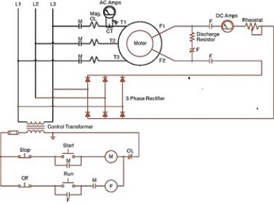
In the accompanying figure, when the stator is energized, the rotor circuit must be open at all times.
Question
Question
In the accompanying figure, the unity power factor of the motor can be found by adjusting the rheostat to obtain a minimum reading on the AC ammeter in the circuit.
A)branch
B)stator
C)main
D)rotor

Unlock Deck
Sign up to unlock the cards in this deck!
Unlock Deck
Unlock Deck
1/10
Play
Full screen (f)
Deck 40: Push-Button Synchronizing
1
In the accompanying figure, the normally open contacts M in the F coil circuit prevent the DC field from being energized before the motor is started.
True
2
The discharge resistor the self-induced voltage from the collapsing DC magnetic field of the rotor windings.
A)dissipates
B)recovers
C)complements
D)increases
A)dissipates
B)recovers
C)complements
D)increases
A
3
The principal difference between synchronous motor control and induction motor control is in the control of the field.
True
4
In the accompanying figure, the ammeter and rheostat control the excitation current.
Unlock Deck
Unlock for access to all 10 flashcards in this deck.
Unlock Deck
k this deck
5
In the accompanying figure, the synchronous motor is started as an induction motor by the start button.
A)pulling
B)releasing
C)disconnecting
D)pressing
A)pulling
B)releasing
C)disconnecting
D)pressing
Unlock Deck
Unlock for access to all 10 flashcards in this deck.
Unlock Deck
k this deck
6
In the accompanying figure, the overlapping normally closed contacts keep the loading resistor in the circuit.
A)F
B)L
C)M
D)T
A)F
B)L
C)M
D)T
Unlock Deck
Unlock for access to all 10 flashcards in this deck.
Unlock Deck
k this deck
7
In the accompanying figure, the rotating magnetic field of the stator acts like a .
A)transformer primary
B)primary resistor starter
C)magnetic primary contactor
D)time-delay relay
A)transformer primary
B)primary resistor starter
C)magnetic primary contactor
D)time-delay relay
Unlock Deck
Unlock for access to all 10 flashcards in this deck.
Unlock Deck
k this deck
8
In the accompanying figure, when the stator is energized, the rotor circuit must be open at all times.
Unlock Deck
Unlock for access to all 10 flashcards in this deck.
Unlock Deck
k this deck
9
There is one basic function of synchronous motor control in starting.
Unlock Deck
Unlock for access to all 10 flashcards in this deck.
Unlock Deck
k this deck
10
In the accompanying figure, the unity power factor of the motor can be found by adjusting the rheostat to obtain a minimum reading on the AC ammeter in the circuit.
A)branch
B)stator
C)main
D)rotor
Unlock Deck
Unlock for access to all 10 flashcards in this deck.
Unlock Deck
k this deck
Unlock Deck
Unlock for access to all 10 flashcards in this deck.