Deck 16: Additional Op-Amp Applications
Full screen (f)
Question
Question
Question
Question
Question
Question
Question
Question
Question
Question
Question
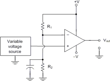
The circuit in Figure has the following values: R1 = 7 kΩ, R2 = 1 kΩ, CB = 1 μF, and supply voltages of ±10 V. What is the value of Vref for this circuit?
A) +1.25 V
B) -1.25 V
C) + 2.5 V
D) -7.5 V
Question
Question
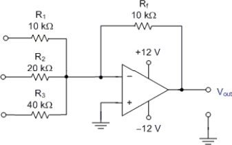
What is the general-class equation for the circuit in Figure?
A) Vout = V1 + 2V2 + 4V3
B) -Vout = V1 + 0.5V2 + 0.25V3
C) -Vout = V1 + 2V2 + 0.25V3
D) None of these are correct.
Question
Question
Question
Question
Question
Question
Question
Question
The circuit in Figure has the following values: R1 = 7 kΩ, R2 = 1 kΩ, CB = 1 μF, and supply voltages of ±10 V. The input is + 1 V. What is the approximate output voltage?
A) + 9 V
B) - 9 V
C) + 5 V
D) - 5 V
Question
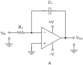
Circuit A is an) .
A) linear amplifier
B) integrator
C) differentiator
D) comparator
Question
The circuit in Figure has the following values: R1=10 kΩ, Rf = 180 kΩ, and C1 = 0.1 μF. Which of the following statements is true?
A) The maximum voltage gain of the circuit equals the ratio of Rf to R1.
B) The maximum voltage gain of the circuit is approximately equal to the AOL rating of the op-amp.
C) The circuit is an inverting amplifier with a bypassed feedback resistor.
D) None of the above statements are true.
Question
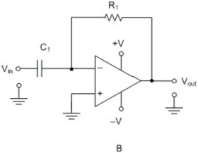
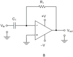
Circuit B is an) .
A) linear amplifier
B) integrator
C) differentiator
D) comparator
Question
The circuit in Figure has the following values: R1=10 kΩ and C1 = 0.1 μF. Which of the following statements is true?
A) The maximum voltage gain of the circuit equals the ratio of Rf to R1.
B) The maximum voltage gain of the circuit is approximately equal to the AOL rating of the op-amp.
C) The circuit is an inverting amplifier with an input coupling capacitor.
D) None of the above statements are true.
Question
The circuit in Figure is an) .
A) differentiator
B) comparator
C) instrumentation amplifier
D) ramp generator
Question
CB is used to
A) filter out power supply current surges.
B) prevent variations in vin from affecting the voltage divider.
C) filter out unwanted stray inductance.
D) filter out unwanted stray capacitance.

Unlock Deck
Sign up to unlock the cards in this deck!
Unlock Deck
Unlock Deck
1/27
Play
Full screen (f)
Deck 16: Additional Op-Amp Applications
1
A summing amplifier may be used as a/an
A) linear amplifier.
B) oscillator.
C) digital-to-analog converter.
D) analog-to-digital converter.
A) linear amplifier.
B) oscillator.
C) digital-to-analog converter.
D) analog-to-digital converter.
digital-to-analog converter.
2
Which of the following can best be described as a high-gain, high CMRR circuit that is used to detect and amplify low-level signals?
A) An op-amp audio amplifier
B) A high-z voltmeter
C) An instrumentation amplifier
D) A subtractor
A) An op-amp audio amplifier
B) A high-z voltmeter
C) An instrumentation amplifier
D) A subtractor
An instrumentation amplifier
3
The output from a differentiator is proportional to
A) the peak value of the input voltage.
B) the rate of change of the input voltage.
C) the rate of change of the input frequency.
D) None of these are correct.
A) the peak value of the input voltage.
B) the rate of change of the input voltage.
C) the rate of change of the input frequency.
D) None of these are correct.
the rate of change of the input voltage.
4
The differentiator can be used to convert a
A) square wave into a triangular wave.
B) square wave into a sine wave.
C) triangular wave into a sine wave.
D) triangular wave into a square wave.
A) square wave into a triangular wave.
B) square wave into a sine wave.
C) triangular wave into a sine wave.
D) triangular wave into a square wave.
Unlock Deck
Unlock for access to all 27 flashcards in this deck.
Unlock Deck
k this deck
5
The ideal output from an op-amp integrator with a square wave input would be a triangular waveform. What is the actual output wave shape?
A) Sinusoidal
B) Exponential
C) Triangular
D) Square
A) Sinusoidal
B) Exponential
C) Triangular
D) Square
Unlock Deck
Unlock for access to all 27 flashcards in this deck.
Unlock Deck
k this deck
6
Which of the following can best be described as a high-gain, minimum distortion, high input impedance, low output impedance circuit operated between 20 Hz and 20 kHz?
A) An op-amp audio amplifier
B) A high-z voltmeter
C) An instrumentation amplifier
D) A subtractor
A) An op-amp audio amplifier
B) A high-z voltmeter
C) An instrumentation amplifier
D) A subtractor
Unlock Deck
Unlock for access to all 27 flashcards in this deck.
Unlock Deck
k this deck
7
The gain of a typical comparator is approximately equal to
A) unity 1).
B) 3 dB.
C) the open-loop voltage gain AOL) of its op-amp.
D) 0 dB.
A) unity 1).
B) 3 dB.
C) the open-loop voltage gain AOL) of its op-amp.
D) 0 dB.
Unlock Deck
Unlock for access to all 27 flashcards in this deck.
Unlock Deck
k this deck
8
A summing amplifier provides an output that is always
A) equal to the difference between its input voltages.
B) equal to the sum of its input voltages.
C) equal or proportional to the sum of its input voltages.
D) None of these are correct.
A) equal to the difference between its input voltages.
B) equal to the sum of its input voltages.
C) equal or proportional to the sum of its input voltages.
D) None of these are correct.
Unlock Deck
Unlock for access to all 27 flashcards in this deck.
Unlock Deck
k this deck
9
The input voltages to the circuit in Figure are as follows: V1 = 2 V, V2 = 4 V, and V3 = 8 V. What is the output voltage from the circuit?
A) +11 V
B) +6 V
C) -11 V
D) -6 V
A) +11 V
B) +6 V
C) -11 V
D) -6 V
Unlock Deck
Unlock for access to all 27 flashcards in this deck.
Unlock Deck
k this deck
10
The comparator may be used as a/an
A) linear amplifier.
B) oscillator.
C) sine wave to rectangular wave converter.
D) rectangular wave to triangular wave converter.
A) linear amplifier.
B) oscillator.
C) sine wave to rectangular wave converter.
D) rectangular wave to triangular wave converter.
Unlock Deck
Unlock for access to all 27 flashcards in this deck.
Unlock Deck
k this deck
11
The circuit in Figure has the following values: R1 = 7 kΩ, R2 = 1 kΩ, CB = 1 μF, and supply voltages of ±10 V. What is the value of Vref for this circuit?
A) +1.25 V
B) -1.25 V
C) + 2.5 V
D) -7.5 V
Unlock Deck
Unlock for access to all 27 flashcards in this deck.
Unlock Deck
k this deck
12
A comparator is a circuit that is used to provide a output when the input voltage is more than a fixed reference voltage.
A) positive; positive; positive
B) positive; negative; positive
C) negative; positive; negative
D) All of these are correct.
A) positive; positive; positive
B) positive; negative; positive
C) negative; positive; negative
D) All of these are correct.
Unlock Deck
Unlock for access to all 27 flashcards in this deck.
Unlock Deck
k this deck
13
What is the general-class equation for the circuit in Figure?
A) Vout = V1 + 2V2 + 4V3
B) -Vout = V1 + 0.5V2 + 0.25V3
C) -Vout = V1 + 2V2 + 0.25V3
D) None of these are correct.
Unlock Deck
Unlock for access to all 27 flashcards in this deck.
Unlock Deck
k this deck
14
Two common-mode inputs to an instrumentation amplifier have identical .
A) amplitude
B) amplitude and phase
C) frequency
D) amplitude and frequency
A) amplitude
B) amplitude and phase
C) frequency
D) amplitude and frequency
Unlock Deck
Unlock for access to all 27 flashcards in this deck.
Unlock Deck
k this deck
15
Instrumentation amplifiers are used to amplify signals.
A) high frequency
B) out of phase
C) high level
D) low level
A) high frequency
B) out of phase
C) high level
D) low level
Unlock Deck
Unlock for access to all 27 flashcards in this deck.
Unlock Deck
k this deck
16
The key to obtaining a triangular output from an integrator with a square wave input is to provide
A) a constant-current charging source for the capacitor.
B) a constant-frequency charging source for the capacitor.
C) a constant-voltage charging source for the capacitor.
D) a short RC time constant.
A) a constant-current charging source for the capacitor.
B) a constant-frequency charging source for the capacitor.
C) a constant-voltage charging source for the capacitor.
D) a short RC time constant.
Unlock Deck
Unlock for access to all 27 flashcards in this deck.
Unlock Deck
k this deck
17
The ideal output from an RC integrator would be a triangular waveform when the input signal is a square wave. What is the actual output wave shape?
A) Sinusoidal
B) Exponential
C) Triangular
D) Square
A) Sinusoidal
B) Exponential
C) Triangular
D) Square
Unlock Deck
Unlock for access to all 27 flashcards in this deck.
Unlock Deck
k this deck
18
A comparator has the following values: RL = 20 kΩ, VS = +10 V, and Vref = +2 V applied to the inverting input). If the noninverting input goes to +3 V, the output voltage
A) will be approximately +9 V.
B) will be approximately -9 V.
C) will be approximately +3 V.
D) cannot be determined without knowing the value of ACL for the circuit.
A) will be approximately +9 V.
B) will be approximately -9 V.
C) will be approximately +3 V.
D) cannot be determined without knowing the value of ACL for the circuit.
Unlock Deck
Unlock for access to all 27 flashcards in this deck.
Unlock Deck
k this deck
19
A summing amplifier has the following values: Rf = 10 kΩ, and R1=R2=R3=R4=40 kΩ. Which of the following statements is true about the circuits?
A) The circuit will not work with the values given.
B) The output will equal the average of the four input voltages.
C) The output will equal the sum of the four input voltages.
D) The output will equal the sum of the squares of the four input voltages.
A) The circuit will not work with the values given.
B) The output will equal the average of the four input voltages.
C) The output will equal the sum of the four input voltages.
D) The output will equal the sum of the squares of the four input voltages.
Unlock Deck
Unlock for access to all 27 flashcards in this deck.
Unlock Deck
k this deck
20
The use of a variable comparator allows for
A) changing the values of VS.
B) processing ultra-high frequency signals.
C) changing the value of Vref.
D) changing the limits of Vout.
A) changing the values of VS.
B) processing ultra-high frequency signals.
C) changing the value of Vref.
D) changing the limits of Vout.
Unlock Deck
Unlock for access to all 27 flashcards in this deck.
Unlock Deck
k this deck
21
The circuit in Figure has the following values: R1 = 7 kΩ, R2 = 1 kΩ, CB = 1 μF, and supply voltages of ±10 V. The input is + 1 V. What is the approximate output voltage?
A) + 9 V
B) - 9 V
C) + 5 V
D) - 5 V
Unlock Deck
Unlock for access to all 27 flashcards in this deck.
Unlock Deck
k this deck
22
Circuit A is an) .
A) linear amplifier
B) integrator
C) differentiator
D) comparator
Unlock Deck
Unlock for access to all 27 flashcards in this deck.
Unlock Deck
k this deck
23
The circuit in Figure has the following values: R1=10 kΩ, Rf = 180 kΩ, and C1 = 0.1 μF. Which of the following statements is true?
A) The maximum voltage gain of the circuit equals the ratio of Rf to R1.
B) The maximum voltage gain of the circuit is approximately equal to the AOL rating of the op-amp.
C) The circuit is an inverting amplifier with a bypassed feedback resistor.
D) None of the above statements are true.
Unlock Deck
Unlock for access to all 27 flashcards in this deck.
Unlock Deck
k this deck
24
Circuit B is an) .
A) linear amplifier
B) integrator
C) differentiator
D) comparator
Unlock Deck
Unlock for access to all 27 flashcards in this deck.
Unlock Deck
k this deck
25
The circuit in Figure has the following values: R1=10 kΩ and C1 = 0.1 μF. Which of the following statements is true?
A) The maximum voltage gain of the circuit equals the ratio of Rf to R1.
B) The maximum voltage gain of the circuit is approximately equal to the AOL rating of the op-amp.
C) The circuit is an inverting amplifier with an input coupling capacitor.
D) None of the above statements are true.
Unlock Deck
Unlock for access to all 27 flashcards in this deck.
Unlock Deck
k this deck
26
The circuit in Figure is an) .
A) differentiator
B) comparator
C) instrumentation amplifier
D) ramp generator
Unlock Deck
Unlock for access to all 27 flashcards in this deck.
Unlock Deck
k this deck
27
CB is used to
A) filter out power supply current surges.
B) prevent variations in vin from affecting the voltage divider.
C) filter out unwanted stray inductance.
D) filter out unwanted stray capacitance.
Unlock Deck
Unlock for access to all 27 flashcards in this deck.
Unlock Deck
k this deck
Unlock Deck
Unlock for access to all 27 flashcards in this deck.