Multiple Choice
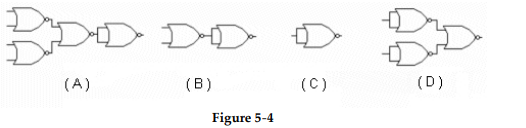
-Which circuit in Figure 5- 4 represents the NOR implementation of an inverter?
A) Figure (A)
B) Figure (B)
C) Figure (C)
D) Figure (D)
Correct Answer:
Verified
Related Questions
Q25: Why are multiple NAND gates often used
Q26: Which of the figures is the correct
Q27: The relationship between a NOR gate and
Q28: Q29: Q31: Which output waveform is correct for the Q32: The point identified as 'X' in this Q33: What is the indication of an open Q34: What is the indication of a short Q35: Unlock this Answer For Free Now! View this answer and more for free by performing one of the following actions Scan the QR code to install the App and get 2 free unlocks Unlock quizzes for free by uploading documents![]()
![]()
![]()