Deck 17: Rlc Circuits and Resonance
ملء الشاشة (f)
سؤال
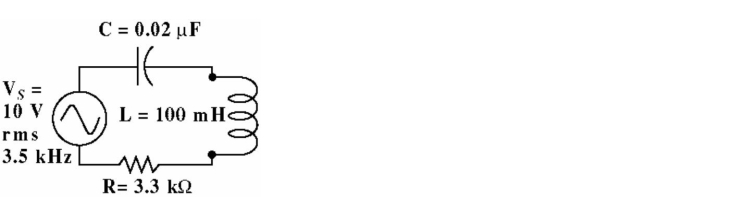
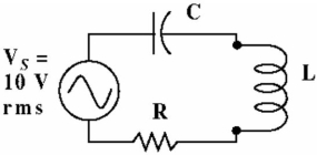 Figure 17-1
If the series circuit in Figure 17-1 is resonant, the inductive and capacitive reactance must be equal.
سؤال
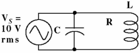
If the parallel circuit in Figure is resonant, the circuit is purely resistive and the phase shift is zero degrees.
سؤال
سؤال
Given the circuit in Figure, the circuit current is:
A) 1 A
B) 198 µA
C) 0.87 mA
D) 100 mA
سؤال
If the parallel circuit in Figure is resonant, the impedance, as seen by the generator will be very high.
سؤال
سؤال
سؤال
سؤال
Figure 17-1If the series circuit in Figure 17-1 is resonant, the impedance, as seen by the generator will be very high.
سؤال
سؤال
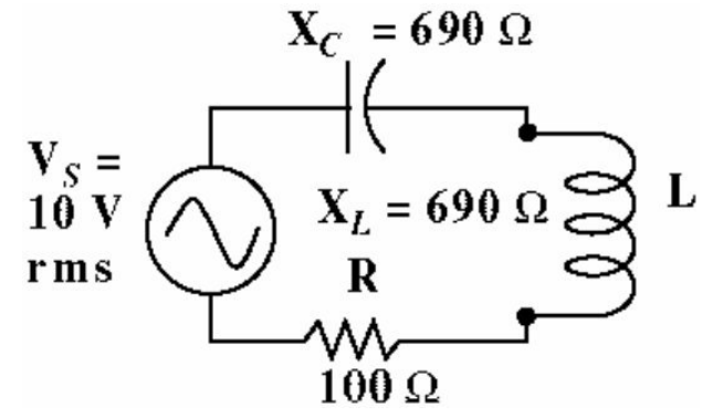
Given the circuit in Figure , the circuit impedance is:
A) 690 Ω
B) 100 Ω
C) 318 Ω
D) 345 Ω
سؤال
If the parallel circuit in Figure is NOT resonant, the impedance will be lower than it is at the resonant frequency.
سؤال
If the parallel circuit in Figure is resonant, increasing the Q will produce a wider bandwidth.
سؤال
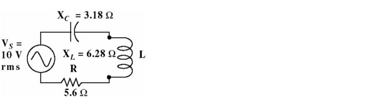
Given the circuit in Figure , the circuit impedance is:
A) 5.88 Ω
B) 6.4 Ω
C) 14.46 Ω
D) 8.1 Ω
سؤال
سؤال
Figure 17-1If the series circuit in Figure 17-1 is resonant, the circuit is purely resistive and the phase shift is zero degrees.
سؤال
If the parallel circuit in Figure is resonant, the inductive and capacitive reactance must be equal.
سؤال
سؤال
Figure 17-1If the series circuit in Figure 17-1 is NOT resonant, the impedance will be lower than it is at the resonant frequency.
سؤال
Figure 17-1If the series circuit in Figure 17-1 is resonant, increasing the Q will produce a wider bandwidth.
سؤال
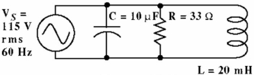
Given the circuit in Figure 17-5, the circuit phase angle is:
A) 90°
B) 34.5°
C) -5.4°
D) -1.3°
سؤال
The current through the capacitor in Figure is:
A) 159.7 mA
B) 434 mA
C) 279.65 mA
D) 4.3 A
سؤال
The Circuit impedance in Figure is:
A) 70.5 Ω
B) 7.55 Ω
C) 265 Ω
D) 33 Ω
سؤال
سؤال
The inductive reactance in Figure is:
A) 2.7 kΩ
B) 750 Ω
C) 2.6 Ω
D) 7.5 Ω
سؤال
سؤال
Given the circuit in Figure 17-4, is the circuit mostly inductive or capacitive?
A) capacitive
B) inductive
سؤال
The capacitive reactance in Figure is:
A) 159.7 Ω
B) 26.53 Ω
C) 265.3 Ω
D) 2.7 kΩ
سؤال
The True power in Figure is:
A) 200.7 W
B) 7.5 W
C) 43.29 W
D) 401 W
سؤال
سؤال
The phase shift between the source voltage VS and total circuit current in Figure is:
A) -46.45°
B) 23.4°
C) -23.4°
D) -76.8°
سؤال
سؤال
سؤال
The Total circuit current in Figure is:
A) 4.3 A
B) 14.87 A
C) 15.2 A
D) 3.5 A
سؤال
The current through the resistor in Figure is:
A) 459.65 mA
B) 15.9 A
C) 350 mA
D) 3.48 A
سؤال
Given the circuit in Figure 17-5, the circuit current is:
A) 7.64 mA
B) 36.9 mA
C) 0.1 A
D) 3.03 mA
سؤال
سؤال
The current through the inductor in Figure is:
A) 27.9 A
B) 15.3 A
C) 153 mA
D) 1.5 A
سؤال
Given the circuit in Figure , the circuit impedance is:
A) 3.3 kΩ
B) 6.94 kΩ
C) 27.1 kΩ
D) 7.07 kΩ
سؤال
Is the circuit in Figure 17-7 at or near resonance?
A) No
B) Yes
سؤال
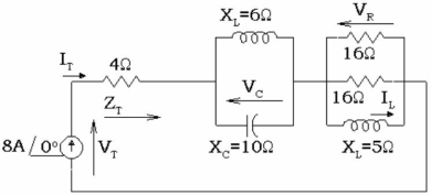
In Figure 17-8, calculate VR.
A) 33.9 V 2-58°
B) 95.0 V 2-39°
C) 33.9 V 258°
D) 95.0 V 239°
سؤال
-calculate ZT.
A) 58
-39°
B) 58
39°
C) 19.6
71.4°
D) 19.6
-71.4°
سؤال
سؤال
سؤال
سؤال
In Figure 17-8, calculate IT.
A) 157 A 2-71.4°
B) 464 A 2-39°
C) 157 A 271.4°
D) 464 A 239°
سؤال
In Figure 17-8, calculate VC.
A) 40 V 260°
B) 40 V 2-60°
C) 120 V 2-90°
D) 120 V 290°
سؤال
سؤال
سؤال
calculate VL across the 5Ω inductive reactance
A) 95.0 V
 39°
39°B) 33.9 V 11ec81bf_ec6d_acdc_bc38_29a3f7414e20_TB34225555_11 -58°
C) 95.0 V 11ec81bf_ec6d_acdc_bc38_29a3f7414e20_TB34225555_11 -39°
D) 33.9 V 11ec81bf_ec6d_acdc_bc38_29a3f7414e20_TB34225555_11 58°

فتح الحزمة
قم بالتسجيل لفتح البطاقات في هذه المجموعة!
Unlock Deck
Unlock Deck
1/50
العب
ملء الشاشة (f)
Deck 17: Rlc Circuits and Resonance
1
Figure 17-1If the series circuit in Figure 17-1 is resonant, the inductive and capacitive reactance must be equal.
True
2
If the parallel circuit in Figure is resonant, the circuit is purely resistive and the phase shift is zero degrees.
True
3
Resonant frequency of a circuit occurs when the inductive reactance is equal to the capacitive reactance.
True
4
Given the circuit in Figure, the circuit current is:
A) 1 A
B) 198 µA
C) 0.87 mA
D) 100 mA
فتح الحزمة
افتح القفل للوصول البطاقات البالغ عددها 50 في هذه المجموعة.
فتح الحزمة
k this deck
5
If the parallel circuit in Figure is resonant, the impedance, as seen by the generator will be very high.
فتح الحزمة
افتح القفل للوصول البطاقات البالغ عددها 50 في هذه المجموعة.
فتح الحزمة
k this deck
6
In a series RLC circuit, above resonance the circuit is more capacitive than it is inductive.
فتح الحزمة
افتح القفل للوصول البطاقات البالغ عددها 50 في هذه المجموعة.
فتح الحزمة
k this deck
7
A parallel resonant circuit has a low impedance at the resonant frequency.
فتح الحزمة
افتح القفل للوصول البطاقات البالغ عددها 50 في هذه المجموعة.
فتح الحزمة
k this deck
8
In a series resonant circuit, current is maximum and impedance is minimum at resonance.
فتح الحزمة
افتح القفل للوصول البطاقات البالغ عددها 50 في هذه المجموعة.
فتح الحزمة
k this deck
9
Figure 17-1If the series circuit in Figure 17-1 is resonant, the impedance, as seen by the generator will be very high.
فتح الحزمة
افتح القفل للوصول البطاقات البالغ عددها 50 في هذه المجموعة.
فتح الحزمة
k this deck
10
A parallel tuned circuit can be used to couple energy from one circuit to another.
فتح الحزمة
افتح القفل للوصول البطاقات البالغ عددها 50 في هذه المجموعة.
فتح الحزمة
k this deck
11
Given the circuit in Figure , the circuit impedance is:
A) 690 Ω
B) 100 Ω
C) 318 Ω
D) 345 Ω
فتح الحزمة
افتح القفل للوصول البطاقات البالغ عددها 50 في هذه المجموعة.
فتح الحزمة
k this deck
12
If the parallel circuit in Figure is NOT resonant, the impedance will be lower than it is at the resonant frequency.
فتح الحزمة
افتح القفل للوصول البطاقات البالغ عددها 50 في هذه المجموعة.
فتح الحزمة
k this deck
13
If the parallel circuit in Figure is resonant, increasing the Q will produce a wider bandwidth.
فتح الحزمة
افتح القفل للوصول البطاقات البالغ عددها 50 في هذه المجموعة.
فتح الحزمة
k this deck
14
Given the circuit in Figure , the circuit impedance is:
A) 5.88 Ω
B) 6.4 Ω
C) 14.46 Ω
D) 8.1 Ω
فتح الحزمة
افتح القفل للوصول البطاقات البالغ عددها 50 في هذه المجموعة.
فتح الحزمة
k this deck
15
A series resonant circuit has a low impedance at the resonant frequency.
فتح الحزمة
افتح القفل للوصول البطاقات البالغ عددها 50 في هذه المجموعة.
فتح الحزمة
k this deck
16
Figure 17-1If the series circuit in Figure 17-1 is resonant, the circuit is purely resistive and the phase shift is zero degrees.
فتح الحزمة
افتح القفل للوصول البطاقات البالغ عددها 50 في هذه المجموعة.
فتح الحزمة
k this deck
17
If the parallel circuit in Figure is resonant, the inductive and capacitive reactance must be equal.
فتح الحزمة
افتح القفل للوصول البطاقات البالغ عددها 50 في هذه المجموعة.
فتح الحزمة
k this deck
18
By increasing the resistance of a coil you can increase the Q of the coil at resonance.
فتح الحزمة
افتح القفل للوصول البطاقات البالغ عددها 50 في هذه المجموعة.
فتح الحزمة
k this deck
19
Figure 17-1If the series circuit in Figure 17-1 is NOT resonant, the impedance will be lower than it is at the resonant frequency.
فتح الحزمة
افتح القفل للوصول البطاقات البالغ عددها 50 في هذه المجموعة.
فتح الحزمة
k this deck
20
Figure 17-1If the series circuit in Figure 17-1 is resonant, increasing the Q will produce a wider bandwidth.
فتح الحزمة
افتح القفل للوصول البطاقات البالغ عددها 50 في هذه المجموعة.
فتح الحزمة
k this deck
21
Given the circuit in Figure 17-5, the circuit phase angle is:
A) 90°
B) 34.5°
C) -5.4°
D) -1.3°
فتح الحزمة
افتح القفل للوصول البطاقات البالغ عددها 50 في هذه المجموعة.
فتح الحزمة
k this deck
22
The current through the capacitor in Figure is:
A) 159.7 mA
B) 434 mA
C) 279.65 mA
D) 4.3 A
فتح الحزمة
افتح القفل للوصول البطاقات البالغ عددها 50 في هذه المجموعة.
فتح الحزمة
k this deck
23
The Circuit impedance in Figure is:
A) 70.5 Ω
B) 7.55 Ω
C) 265 Ω
D) 33 Ω
فتح الحزمة
افتح القفل للوصول البطاقات البالغ عددها 50 في هذه المجموعة.
فتح الحزمة
k this deck
24
At resonance the power factor is:
A) negative
B) 1
C) M5
D) zero
A) negative
B) 1
C) M5
D) zero
فتح الحزمة
افتح القفل للوصول البطاقات البالغ عددها 50 في هذه المجموعة.
فتح الحزمة
k this deck
25
The inductive reactance in Figure is:
A) 2.7 kΩ
B) 750 Ω
C) 2.6 Ω
D) 7.5 Ω
فتح الحزمة
افتح القفل للوصول البطاقات البالغ عددها 50 في هذه المجموعة.
فتح الحزمة
k this deck
26
At frequencies well above and below the resonant frequency, the series RLC circuit looks above resonance, and the parallel RLC circuit looks below resonance.
A) like an open, like a short
B) like a short, like an open
C) inductive, inductive
D) inductive, capacitive
A) like an open, like a short
B) like a short, like an open
C) inductive, inductive
D) inductive, capacitive
فتح الحزمة
افتح القفل للوصول البطاقات البالغ عددها 50 في هذه المجموعة.
فتح الحزمة
k this deck
27
Given the circuit in Figure 17-4, is the circuit mostly inductive or capacitive?
A) capacitive
B) inductive
فتح الحزمة
افتح القفل للوصول البطاقات البالغ عددها 50 في هذه المجموعة.
فتح الحزمة
k this deck
28
The capacitive reactance in Figure is:
A) 159.7 Ω
B) 26.53 Ω
C) 265.3 Ω
D) 2.7 kΩ
فتح الحزمة
افتح القفل للوصول البطاقات البالغ عددها 50 في هذه المجموعة.
فتح الحزمة
k this deck
29
The True power in Figure is:
A) 200.7 W
B) 7.5 W
C) 43.29 W
D) 401 W
فتح الحزمة
افتح القفل للوصول البطاقات البالغ عددها 50 في هذه المجموعة.
فتح الحزمة
k this deck
30
In a series LC circuit, L = 100 µH, C = 0.047 µF, and f = 150 kHz. The value of ZT is:
A) 72
90°
B) 36
45°
C) -72
-90°
D) 72
-90°
A) 72
90°
B) 36
45°
C) -72
-90°
D) 72
-90°
فتح الحزمة
افتح القفل للوصول البطاقات البالغ عددها 50 في هذه المجموعة.
فتح الحزمة
k this deck
31
The phase shift between the source voltage VS and total circuit current in Figure is:
A) -46.45°
B) 23.4°
C) -23.4°
D) -76.8°
فتح الحزمة
افتح القفل للوصول البطاقات البالغ عددها 50 في هذه المجموعة.
فتح الحزمة
k this deck
32
Is the circuit in Figure 17-5, at or very close to resonance?
A) Yes
B) No
A) Yes
B) No
فتح الحزمة
افتح القفل للوصول البطاقات البالغ عددها 50 في هذه المجموعة.
فتح الحزمة
k this deck
33
Apparent power in an RLC circuit is equal to total voltage times total current when:
A) the circuit is not at resonance
B) the circuit is at resonance.
C) it is a series or parallel circuit
D) all of the above
A) the circuit is not at resonance
B) the circuit is at resonance.
C) it is a series or parallel circuit
D) all of the above
فتح الحزمة
افتح القفل للوصول البطاقات البالغ عددها 50 في هذه المجموعة.
فتح الحزمة
k this deck
34
The Total circuit current in Figure is:
A) 4.3 A
B) 14.87 A
C) 15.2 A
D) 3.5 A
فتح الحزمة
افتح القفل للوصول البطاقات البالغ عددها 50 في هذه المجموعة.
فتح الحزمة
k this deck
35
The current through the resistor in Figure is:
A) 459.65 mA
B) 15.9 A
C) 350 mA
D) 3.48 A
فتح الحزمة
افتح القفل للوصول البطاقات البالغ عددها 50 في هذه المجموعة.
فتح الحزمة
k this deck
36
Given the circuit in Figure 17-5, the circuit current is:
A) 7.64 mA
B) 36.9 mA
C) 0.1 A
D) 3.03 mA
فتح الحزمة
افتح القفل للوصول البطاقات البالغ عددها 50 في هذه المجموعة.
فتح الحزمة
k this deck
37
The lower and upper end of the band width of a series RLC circuit is where the current has fallen to of the maximum.
A) 70.7%
B) 63.6%
C) 29.3%
D) 50%
A) 70.7%
B) 63.6%
C) 29.3%
D) 50%
فتح الحزمة
افتح القفل للوصول البطاقات البالغ عددها 50 في هذه المجموعة.
فتح الحزمة
k this deck
38
The current through the inductor in Figure is:
A) 27.9 A
B) 15.3 A
C) 153 mA
D) 1.5 A
فتح الحزمة
افتح القفل للوصول البطاقات البالغ عددها 50 في هذه المجموعة.
فتح الحزمة
k this deck
39
Given the circuit in Figure , the circuit impedance is:
A) 3.3 kΩ
B) 6.94 kΩ
C) 27.1 kΩ
D) 7.07 kΩ
فتح الحزمة
افتح القفل للوصول البطاقات البالغ عددها 50 في هذه المجموعة.
فتح الحزمة
k this deck
40
Is the circuit in Figure 17-7 at or near resonance?
A) No
B) Yes
فتح الحزمة
افتح القفل للوصول البطاقات البالغ عددها 50 في هذه المجموعة.
فتح الحزمة
k this deck
41
In Figure 17-8, calculate VR.
A) 33.9 V 2-58°
B) 95.0 V 2-39°
C) 33.9 V 258°
D) 95.0 V 239°
فتح الحزمة
افتح القفل للوصول البطاقات البالغ عددها 50 في هذه المجموعة.
فتح الحزمة
k this deck
42
-calculate ZT.
A) 58
-39°
B) 58
39°
C) 19.6
71.4°
D) 19.6
-71.4°
فتح الحزمة
افتح القفل للوصول البطاقات البالغ عددها 50 في هذه المجموعة.
فتح الحزمة
k this deck
43
Half-power frequencies
A) determine the pass band.
B) determine bandwidth.
C) determine selectivity.
D) all of the above
E) none of the above
A) determine the pass band.
B) determine bandwidth.
C) determine selectivity.
D) all of the above
E) none of the above
فتح الحزمة
افتح القفل للوصول البطاقات البالغ عددها 50 في هذه المجموعة.
فتح الحزمة
k this deck
44
In a series LC circuit, VL = 8.3 V and VC = 10.6 V. VS = .
A) -2.3 V 2-90°
B) 8.3 V 2-90°
C) -2.3 V 290°
D) 2.3 V 2-90°
A) -2.3 V 2-90°
B) 8.3 V 2-90°
C) -2.3 V 290°
D) 2.3 V 2-90°
فتح الحزمة
افتح القفل للوصول البطاقات البالغ عددها 50 في هذه المجموعة.
فتح الحزمة
k this deck
45
The center frequency of a band-pass filter is always equal to the .
A) geometric mean average of the cutoff frequencies
B) 3-dB frequency
C) bandwidth divided by Q
D) bandwidth
A) geometric mean average of the cutoff frequencies
B) 3-dB frequency
C) bandwidth divided by Q
D) bandwidth
فتح الحزمة
افتح القفل للوصول البطاقات البالغ عددها 50 في هذه المجموعة.
فتح الحزمة
k this deck
46
In Figure 17-8, calculate IT.
A) 157 A 2-71.4°
B) 464 A 2-39°
C) 157 A 271.4°
D) 464 A 239°
فتح الحزمة
افتح القفل للوصول البطاقات البالغ عددها 50 في هذه المجموعة.
فتح الحزمة
k this deck
47
In Figure 17-8, calculate VC.
A) 40 V 260°
B) 40 V 2-60°
C) 120 V 2-90°
D) 120 V 290°
فتح الحزمة
افتح القفل للوصول البطاقات البالغ عددها 50 في هذه المجموعة.
فتح الحزمة
k this deck
48
In a series RLC circuit, R = 1.1 kΩ, XL = 1.6 kΩ, and XC = 2.9 kΩ. ZT = .
A) 4.6 k
-50°
B) 4.6 k
50°
C) 1.7 k
50°
D) 1.7 k
-50°
A) 4.6 k
-50°
B) 4.6 k
50°
C) 1.7 k
50°
D) 1.7 k
-50°
فتح الحزمة
افتح القفل للوصول البطاقات البالغ عددها 50 في هذه المجموعة.
فتح الحزمة
k this deck
49
If the bandwidth of a filter increases, .
A) ripples appear in the stopband
B) the roll-off rate increases
C) Q decreases
D) the center frequency decreases
A) ripples appear in the stopband
B) the roll-off rate increases
C) Q decreases
D) the center frequency decreases
فتح الحزمة
افتح القفل للوصول البطاقات البالغ عددها 50 في هذه المجموعة.
فتح الحزمة
k this deck
50
calculate VL across the 5Ω inductive reactance
A) 95.0 V
39°B) 33.9 V 11ec81bf_ec6d_acdc_bc38_29a3f7414e20_TB34225555_11 -58°
C) 95.0 V 11ec81bf_ec6d_acdc_bc38_29a3f7414e20_TB34225555_11 -39°
D) 33.9 V 11ec81bf_ec6d_acdc_bc38_29a3f7414e20_TB34225555_11 58°
فتح الحزمة
افتح القفل للوصول البطاقات البالغ عددها 50 في هذه المجموعة.
فتح الحزمة
k this deck
فتح الحزمة
افتح القفل للوصول البطاقات البالغ عددها 50 في هذه المجموعة.